大家好,今天分享一篇关于 XBAR 的论文,XBAR是 Resnant 公司最新提出的一种新型 BAW 滤波器技术,可以工作在更高的频率,并提供更优的滤波器性能。
Hello everyone, today share a paper about XBAR, XBAR is a new BAW filter technology proposed by Resnant Company, which can operate at higher frequencies and provide better filter performance.
Hello everyone, today share a paper about XBAR, XBAR is a new BAW filter technology proposed by Resnant Company, which can operate at higher frequencies and provide better filter performance.
Hello everyone, today share a paper about XBAR, XBAR is a new BAW filter technology proposed by Resnant Company, which can operate at higher frequencies and provide better filter performance.
这篇论文题目为:5GHz laterally-excited bulk-wave resonators (XBARs) based on thin platelets of lithium niobate
作者为:V. Plessky, S. Yandrapalli, P.J. Turner, L.G. Villanueva, J. Koskela, R.B. Hammond
原文地址:https://ietresearch.onlinelibrary.wiley.com/doi/10.1049/el.2018.7297
Original address:https://ietresearch.onlinelibrary.wiley.com/doi/10.1049/el.2018.7297
Original address:https://ietresearch.onlinelibrary.wiley.com/doi/10.1049/el.2018.7297
Original address:https://ietresearch.onlinelibrary.wiley.com/doi/10.1049/el.2018.7297
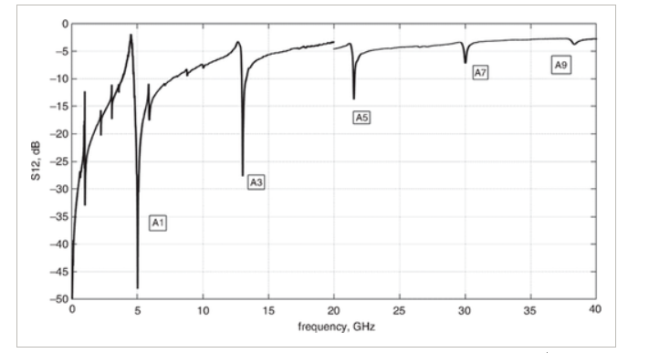
In a free-standing 400-nm-thick platelet of crystalline ZY-LiNbO3, narrow electrodes (500 nm) placed periodically with a pitch of a few microns can eXcite standing shear-wave bulk acoustic resonances (XBARs), by utilising lateral electric fields oriented parallel to the crystalline Y-axis and parallel to the plane of the platelet. The resonance frequency of ∼4800 MHz is determined mainly by the platelet thickness and only weakly depends on the electrode width and the pitch. Simulations show quality-factors (Q) at resonance and anti-resonance higher than 1000. Measurements of the first fabricated devices show a resonance Q-factor ∼300, strong piezoelectric coupling ∼25%, (indicated by the large Resonance-antiResonance frequency spacing, ∼11%) and an impedance at resonance of a few ohms. The static capacitance of the devices, corresponds to the imaginary part of the impedance ∼100 Ω. This device opens the possibility for the development of low-loss, wide band, RF filters in the 3–6 GHz range for 4th and 5th generation (4G/5G) mobile phones. XBARs can be produced using standard optical photolithography and MEMS processes. The 3rd, 5th, 7th, and 9th harmonics were observed, up to 38 GHz, and are also promising for high frequency filter design.
The expansion of mobile phone services and networks, drives the need for progressively wider and higher frequency bands. New services currently going into operation require frequencies in the range of 3.3–3.8 GHz (B78), 3.3–4.2 GHz (B77), 4.4–5.0 GHz (B79), 24.25–29.5 GHz (B257, B258, B261), and 37–40 GHz (B260), with much wider absolute and relative bandwidths than legacy services. Since modern mobile phones must operate in many frequency bands, they demand a large number (20+) of compact, high-performance filters. Currently, for frequencies below 3 GHz, these filters are realised using ladder filters based on surface acoustic wave (SAW) resonators or bulk acoustic wave (BAW) resonators. For the 3–5 GHz range, SAW devices require increasingly narrower electrodes resulting in a higher loss, reduced power handling, and more expensive lithography. BAWs have relatively small piezoelectric coupling and have difficulty supporting the wider bandwidths required. Thus, new acoustic wave filter solutions addressing the loss, power, and bandwidth needs above 3 GHz will be attractive. This Letter shows a potential path to such solutions. It is inspired by Kadota's results [1] on Lamb modes in thin LiNbO3 layers, by Murata's Incredibly High Performance (IHP) wafer technology [2] for SAW devices and by recent developments in MEMS [3].
In their Letter, Kadota and Ogami [1] experimentally demonstrate a resonator based on a 395-nm-thick ZX-cut LN plate exploiting the asymmetric Lamb mode (A1). The resonator had a high-resonance frequency (fr) of 5.44 GHz, a wide relative bandwidth of 12%, and a high-impedance ratio of 62 dB at fr and fa. This demonstrated a 5 GHz acoustic device that did not push the limits of optical lithography. However, the measured Q-factor at fr was only 70, unacceptably low for low-loss filter applications.
Thin monocrystalline lithium tantalate (LT) layers with micron thickness on a thick carrier substrate are used in Murata's IHP SAW technology [2]. The device operation is based on waveguiding of quasi-shear waves in the thin LT layer on a ‘fast’ substrate. Low losses are achieved due to the suppression of the ‘leaky’ bulk-wave component radiated into the substrate and, fortunately, the cut also has a low diffraction loss. In combination with relatively high piezo-coupling and low TCF, IHP SAW devices have been designed with excellent characteristics. Resonator Q values ∼4000 at 2 GHz and 2000 at 3.5 GHz have been estimated, approximately four times higher than for typical ‘leaky-wave’ SAW. However, pushing to 5 GHz remains a challenge for fabricating quarter-wave electrodes by optical lithography. Also, non-periodic devices such as CRF/DMS may have waves scattered from the waveguide and experience corresponding increased losses [4]. IHP SAW is enabled by advanced methods for wafer bonding and transfer of thin crystalline LiTaO3 or LiNbO3 layers of the desired orientation onto different substrates [5].
The recent work by Gong and co-workers [3] on 5 GHz MEMS structures exploiting A1 Lamb modes in crystalline LN platelets have demonstrated high phase velocity, a relatively high Q-factor and excellent coupling K2, >20%. The devices use only a few electrodes on a suspended micron-size platelet and generally exhibit strong spurious plate modes due to edge reflections and high impedance levels (small ∼fF static capacitance), thus eliminating the devices as candidates for mobile phone filters.
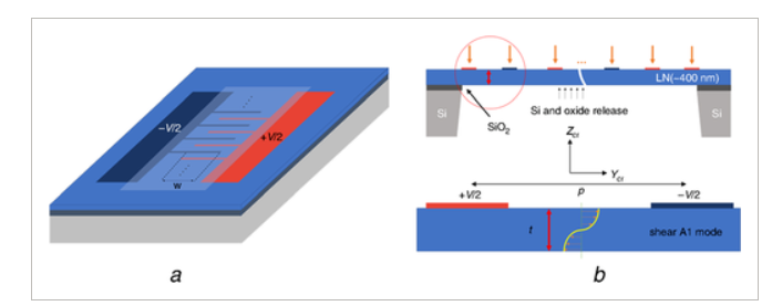
In this Letter, we propose a device including a periodic structure of many 100 nm-thick × 500 nm-wide Al electrodes, spaced at p ≅ 3–5 μm, on a suspended LN platelet of thickness t ≅ 400 nm having fixed edges as shown in Fig. 1. Since the electrode pitch p is significantly larger than its width or the LN platelet thickness t, the acoustic resonance occurs almost exclusively in the free-standing LN platelet zone between the electrodes.

figure1 Schematic diagram of the device structure with crystalline Z-axis perpendicular to the platelet surface; the electrodes are perpendicular to the Y crystal axis
a Top view showing aperture, bus bar and membrane window
b Cross-sectional view with Y crystal axis in the horizontal direction
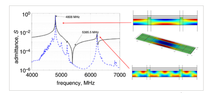
We use ion-sliced monocrystalline LN layers on Si substrates that are now commercially available [5]. Due to the strong e24 piezoelectric coefficient, the ZY orientation of LN for the platelet is suitable for lateral excitation of standing wave in the Z-direction having displacements in the Y-direction (Fig. 1b). The electrodes of alternating polarity create a predominantly-horizontal electric field. We use a rather large pitch p≫t of 3 μm (and 5 μm) in simulated and manufactured devices. A simulation of one such structure is shown in Fig. 2. The simulation was done using our recently developed FEM ‘hierarchical cascading’ approach [6], which is very fast compared to COMSOL for 2D simulations and includes electric and acoustic material losses.


figure2 FEM simulation; the structure with pitch p = 3 μm, aperture W = 20 μm, and a number of electrodes Nt = 51. The insets show the horizontal component of the displacement
The simulations show the impedance at the resonance of the order of 1 Ω, and an imaginary impedance on the order of 100*j Ω away from resonance. These parameters can support the design of low-loss ladder-type filters for mobile phones. The relative Resonance-antiResonance (RaR) frequency separation which determines the low-loss filter passband width is around 11–12%. This is large compared to the 3% typical for AlN-based FBARs. The simulations show excellent Q-factors at resonance and anti-resonance larger than 1000 at ∼5 GHz, inclusive of the resistivity of the electrodes. We describe the main resonance as a shear, bulk-wave, fundamental-mode, platelet resonance (with the platelet thickness t ≅ λ/2, Fig. 1b), with displacements in the crystalline Y-direction, horizontal in Fig. 1b. Shown in the inset in Fig. 2, the results of 3D simulations of a periodic, finite-aperture structure illustrate the distribution of horizontal displacements on the platelet surface. The main vibration mode is concentrated between electrodes where the electric field vector has a large component in the direction perpendicular to the electrodes. It is remarkable that the electrodes have practically no vibrations and stresses inside them and thus the usually-high acoustic loss in the Al metal can be avoided.
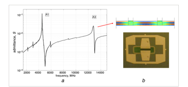
If the plate surfaces were completely free, without electrodes, the mode polarisation could be classified as an anti-symmetric Lamb mode of the 1st order, A1, with velocity ∼15,000 m/s, for p = 3 μm (or ∼25,000 m/s for p = 5 μm). Such a fast phase velocity is a geometric effect – the wavefronts of a shear wave reflected up and down propagate almost vertically. The high phase velocity corresponds to almost zero group velocity: vertically reflected waves do not carry energy horizontally. In the case of a finite structure, FEM simulations show no wave propagation outside the electrode array. In this device, the discussed main resonance, as well as other resonating modes, are present. Although not shown in Fig. 2 above, the 3rd, …, 9th ‘vertical’ harmonics are simulated and observed experimentally (see Figs. 3 and 4). These modes correspond to the situation when the plate thickness t = n × λ /2 (n = 3, 5, …), where the wavelength λ is that of a vertically propagating shear wave. One can say that anti-symmetric Lamb modes A3, A5, A7, A9 are exited between the electrodes.


Figure3 Manufactured device performance
a Measured admittance curve with simulated higher-order A3 mode
b Photo of the manufactured device: bright areas are Al contacts, green area is LiNbO3 platelet, the interdigitated electrodes look black

CD>0.5 μm at 5 GHz frequency range. The devices can be manufactured with standard optical lithography.
Extremely high Q-factors can be obtained due to the use of shear waves, and the absence of electrode metal in areas with high stresses.
The uniquely strong coupling can be achieved. The addition of a SiO2 layer between electrodes can be used for temperature stabilisation and for control and tuning of the resonance frequency and coupling.
The solid LiNbO3 platelet attached from all sides is mechanically stable and provides better heat dissipation than if suspended in a few points such as anchors in MEMS devices.
1Kadota, M., Ogami, T.: ‘5.4 GHz lamb wave resonator on LiNbO3 thin crystal plate and its application’, Jpn. J. Appl. Phys., 2011, 50, (78), pp. 1– 4
2Takai, T., Iwamoto, H., Takamine, Y. et. al.,: ‘ I.H.P. SAW technology and its application to microacoustic components (invited)’. IEEE Int. Ultrasonics Symp. (IUS), Washington, DC, USA, September 2017, pp. 1– 8
3Yang, Y., Lu, R., Manzaneque, T. et. al.,: ‘ Toward Ka band acoustics: lithium niobate asymmetrical mode piezoelectric MEMS resonators’. IEEE Int. Frequency Control Symp., Olympic Valley, California, USA, May 2018
4Plessky, V., Koskela, J., Willemsen, BA. et. al.,: ‘ FEM modeling of an entire 5-IDT CRF/DMS filter’. IEEE Int. Ultrasonics Symp. (IUS), Washington, DC, USA, September 2017, pp. 1– 5, doi: 109/ULTSYM.2017.8091824
5 NanoLN: ‘ LN thin film on insulator’. Available at http://www.nanoln.com/en/pinfo.asp?ArticleID=32, accessed September 2018
6Koskela, J., Maniadis, P., Willemsen, BA. et. al.,: ‘ Hierarchical cascading in 2D FEM simulation of finite SAW devices with periodic block structure’. IEEE Int. Ultrasonics Symp. (IUS), Tours, France, September 2016, pp. 1– 4
 最前沿的电子设计资讯